What component Makeup the PLC
- May 29, 2020
- 3 min read
In my previous article, I have covered basic of the PLC and its programming language type and famous brand of the PLC. Click here to read basic of the PLC.
In this article, I will further cover component which makes up the PLC. Component mostly remains the same od every manufacturer but the placement of the component can vary manufacturer to the manufacturer.
If you are looking for a more detailed study on the PLC and its history, you may click here. I keep simple and make an article brief enough to make people understand.
The component that makes up the PLC:
1. Power supply
2. CPU
3. Digital input module
4. Digital output module
5. Analog input module
6. Analog output module
Above listed components are common in every manufacturer, but in the Siemens PLC slot "3" is reserved for Interface Module (IM) in a software environment, which is used to communicate with another rack and for remote I/Os. If you are not using IM then in hardware you doesn't need to keep slot empty but in the software, you have to keep slot empty.
Additionally, you can use a Communication Processor (CP) to communicate with other automation facilities.
For high-speed counting, Siemens use special Functional Module (FM) which contains inbuilt CPU provides the capability to capture fast action process.
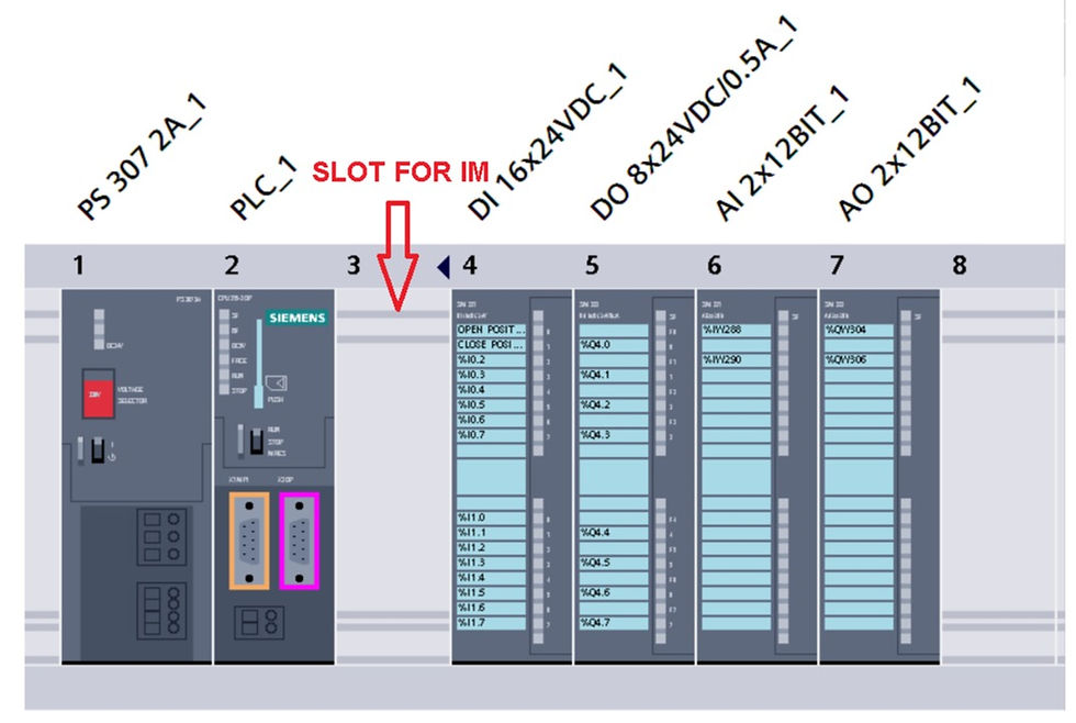
You can see above-displayed image contain typical setup for the Siemens PLC. In the below image, you can see the software configuration of Allen-Bradley PLC. This all component together makeup the PLC.

Let understand each module in brief
1. Power supply
It is used to provide supply to power up another module. Most commonly 24 VDC power supply is used. But in some cases 230 VAC used, but it converts that 230 VAC to 24 VDC internally.
It is important to calculate voltage and amps require to work with an application, as per calculation you can choose a power supply with require amps.
2. CPU
Heart of the PLC. CPU process the logic based on program written by a user. The different manufacturer has the different capability of CPU from a lower range to a higher range used based on an application.
For example, Siemens has a CPU like 300, 400, 1200 and 1500 all have their capability based on application.
3. Digital Input
Digital input is used with digital devices like switches, pushbutton, all kind of switches like pressure, level, temperature, flow, etc. So, a device which has only two states used with digital input module.
4. Digital Output
Digital output module used to connect output device like solenoid valve, on/off valve, motor, conveyor, pump, contactor, relay.
5. Analog Input
Values which doesn't have two states but vary with different range of value are called analog devices.
Analog input like all kind of transmitter, humidity sensor, CO2 sensors, etc. They provide 4-20 mA DC signal which then proceeds by PLC.
6. Analog Output
Analog output like a control valve, VFD which get signal from analog input to operate within a range.
This is a very simple explanation to make people learn easily. Still, you find any problem with this article or you want to learn more then don't forget to do the comment. Your comment is valuable to me. I will respond to you as soon as possible with the best knowledge I have.
If you are looking for more article on PLC like an explanation of instruction in Siemens and Allen-Bradley PLCs, Programming Example, troubleshooting methods, how to create a new project, how to set up remote I/Os and many other articles related to the PLC then please do comment on which article I should write the post. Your recommendation would be helpful for me, which makes me write more and more about field of instrumentation and automation.


Comments