TIMER IN SIMATIC MANAGER (STL & LD)
- Jan 24, 2021
- 2 min read
In this article, we will learn timer in Simatic Manager using STL programming language of Siemens PLC.
Most people know about ladder logic but few people have an idea about STL language.
If instructions are the same then the only conversion from a ladder to STL is possible. But most of STL instructions are different then ladder.
In Siemens Simatic manager and in TIA portal you can see five types of timer. Name of the timer is as below.
Name of the timer:
1. S_PULSE (Pulse Timer)
2. S_PEXT (Extended Pulse Timer)
3. S_ODT (On delay-Timer)
4. S_ODTS (Retentive or stored on delay-timer)
5. S_OFFDT (OFF delay timer)
- S_PULSE: In S_PULSE timer, It will turn ON for a specified time interval while transitioning of input from false to true.
- S-PEXT: Like S_PULSE timer it works exactly the same but while turning OFF the input it will remain on until timer complete it's timing.
- S_ODT: In ON delay timer the output will only turn ON after timer complete it's timing.
- S_ODTS: It works exactly the same as ON delay timer, the only difference is there this is a retentive timer. So, despite de-energizing the input, the output will remain ON.
- S_OFFDT: In the OFF delay timer, the output will energize when transition of the input from true to false.
In STL if you want to write a code you have to use the below symbol for a timer.
1. SP (Pulse)
2. SE (Extended pulse)
3. SD (On delay)
4. SS (Retentive on delay)
5. SF (OFF delay)
Let understand STL programming of the timer with an example.

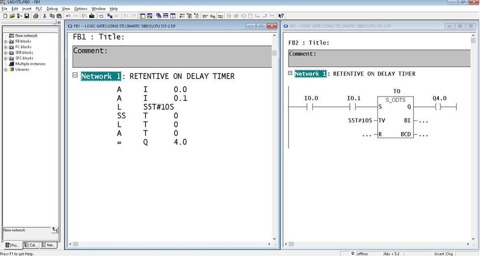
I have written a code for a condition where I want two different input to energize together to turn ON the timer. After a specified time interval output will energize because I have used retentive ON delay timer here.
I have used two input I0.0 and I0.1 and output Q4.0 with one retentive on delay timer.
In the above window, you can see that I have programmed in both languages to make things easier to understand.
EXPLANATION:
In the First two-line of code, I have used two input with A (AND). Now, to use timer we have to first load timer value in S5 format.
In the next line of code, I have used “SS” which is retentive ON delay timer, So the output will only energize after timer complete it's timing.
In the next line of code, I have a load number of the timer or you can say a notation(T0) to monitor a timer value.
In the next line of code is to examine the state of timer true/false.
The last line of code is for the output represent by “=” sign.
Hope, you like this article. If you do so then please like and share amongst your network.
If you want to see more programming related article then kindly put your comment down below an article.


Comments