What Instrumentation Loop Diagram Is (LOOP DIAGRAM)?
- Feb 10, 2021
- 4 min read
In this series of article, I am giving you a detailed study of different types of instrumentation design documents.
Till now we have discussed Process Flow Diagram(PFD), Block Flow Diagram(BFD) and Piping and Instrumentation Diagram(P&ID).
In this article, we will learn what instrumentation loop diagram is in detail with a practical explanation. You will also learn classification of loop diagram, loop diagram connection.
LOOP DIAGRAM:
Instruments loop diagram shows a connection from field to control system. We can use a loop diagram while troubleshooting instruments to see correct wiring and we can also use it at pre-commissioning and commissioning stage.
Instruments loop diagram could be a connection between,
1 Field instruments to control room.
2. Signal from Control Panel to Control System
3. Signal from MCC to Control System
4. Signal from one Control System to another Control System
Those who have worked with instruments loop diagram knows that loop diagram is divided into two parts. One is the field side and another is the control room side.
Fieldside is again divided into two parts. one is field area where an instrument is located and another junction box where wiring is connected.
Control room side you can find Marshalling cabinet. In marshalling cabinet it has two part one is marshalling cabinet front and another is marshalling cabinet rear.
To draw loop diagram, one needs information like tag number of the instrument, JB number, terminal block number, Marshalling cabinet detail and its termination detail, system card and I/O details.
In the below image you can see a sample of instrument loop diagram of Analog Input(Pressure Transmitter)
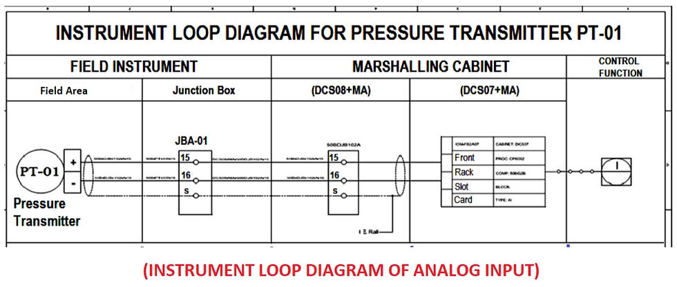
In the above-mentioned loop diagram, you can see the flow of wiring from field to control room.
Here, from the image, you might feel that wiring starts from the transmitter end to create a loop but, the actual flow starts from a marshalling cabinet.
Inside Marshalling cabinet you can find two bus bar "+" and "-". Wiring starts from "+" to one of connection in marshalling cabinet ten flowing through Junction box to the transmitter and from"-" of the transmitter to JB to the marshalling cabinet.
This above scenario is only true while working with Analog devices both Inputs and Outputs.
While troubleshooting process one can easily identify by following number written on its loop diagram and on wiring itself.
Classification of Loop diagram:
1. Simple classification can be done as PCS/DCS loop diagram for controlling and indication
2. ESD loop diagram for emergency shutting down of instruments
3. F& G loop diagram for fire and gas-related alarms/operations
This can be further classified into subcategories as AI(Analog Input)/AO(Anaog Output)/DI(Digital Input)/DO(Digital Output) loops
All signals (voltage or current) is considered with respect to control room. Thus if a signal is going out of control room for closing opening control valve and on/off valve it is considered as an output signal.
Examples are Analog and digital outputs AO/DO and if signals come into control room giving the indication, position, level, temperature, pressure etc it is considered as input signals examples are AI and DI signals.
Analog signals have many values which change with respect to time like 4 to 20mA for measuring pressure, temperature, level, flow, etc.
while digital signal will have only binary values like 0 (off) and 1(on) conditions of on/off valve, the status of on/off valve, closed open condition of switches, motor on/off condition etc. Let's consider the three loops individually.
PCS/DCS(Process Control system/Distributed Control System) loop:
This can be further classified as PCS AI (Process Control System- Analog Input) PCS DI (Process Control System -Digital Input) PCS AO (Process Control System- Analog Output) PCS DO(Process Control System- Digital Output)
ESD(Emergency Shut down) loop:
This can be further classified as ESD DO( Emergency Shutdown Device- Digital Output) ESD DI ( Emergency Shutdown Device- Digital Input) ESD AI ( Emergency Shutdown Device- Analog Input) ESD AO (generally not used because in case of an emergency we need immediate action which can be achieved through ESD DO signal)
F&G(Fire and Gas) Loop:
FGS DO (Fire and Gas System- Digital Output) FGS DI (Fire and Gas System-Digital Input) FGS AI (Fire and Gas System -Analog Input) FGS AO (generally not used because in case of an emergency we need immediate action which can be achieved through FGS DO signal)
Loop diagram shows instrument (in a symbol) and its terminal numbers which are to be connected, instrument cable 8 number, junction box 1 number, the terminal number assigned for the specified instrument, multi-pair cable and pair number, marshalling cabinet number, terminal number in marshalling cabinet, control system details (rack, slot, I/O channel).
It also clearly indicates the location of each equipment by means of borderline as a limit.
Loop Diagram usually shows a single control loop which means it could only contains just one input (sensor to control system), just one output (control system to a final element) or combination of both.
In the next article, we will learn three above mentioned loop diagram in detail. If you like this article then do like and you can also ask a question in the below comment section.
Credit: some of the topic and image is taken from instrument design book.


Comments