FORCE BALANCE PNEUMATIC POSITIONER :
- May 5, 2020
- 2 min read
As of now SMART and electronic type of positioner are slowly replacing pneumatic type positioner, but still, such pneumatic positioner is existed with their complex but easy to understand operating method.
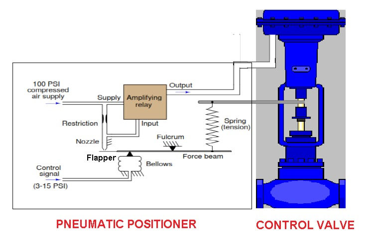
Here in this article, I will cover a force balance type pneumatic actuator. Following is the figure of the force balance type of pneumatic positioner.

Here control signal is 3-15 psi, coming from I/P convertor or from the pneumatic controller.
Compressed air supply of 100 psi is used here for example, but in most cases, 20 psi of air supply is used.
Now at 3 psi of control signal, the gap between flapper and nozzle stays larger allow air to escape from there. Air supply let consider 20 psi will pass through the restriction, due to the gap is larger air pressure escapes through nozzle and remaining pressure will enter through an input port and in amplifying relay, then output is sent to the actuator.
At 15 psi of control signal, due to high pressure, it pushes flapper near to nozzle decreasing back-pressure thus increasing main air supply which passes through amplifying relay and provide output to actuator.
So, at 15 psi when output is sent to an actuator, due to air provide at the downside of the actuator valve lifts up in a fully open position. At 3 psi valve remain close.
Here, when a valve lifts up it stretches spring, applying additional force to the right side of the force beam. When this additional force balances the bellow force, the system stabilizes. Like a two-team of people pulling a rope as long as force can't be equal.

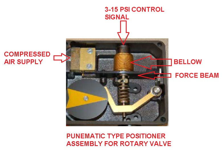
Above shown figure is of pneumatic positioner used to operate a rotary valve. When air pressure is applied on bellow it pushes force beam.
That yellow arrow is an indication of the position. As pressure increases force on the beam will create the force on spring, Thus more pressure requires to balance the force.


Comments